
Differential Pressure Transmitter Construction
A differential pressure transmitter has three functional parts.
1) Direct Pressure sensing element (located in the lower housing).
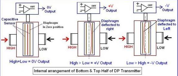
The majority of industrial DP Transmitters are fitted with diaphragm as the pressure sensing element. This diaphragm is a mechanical device. It is placed in between the two pressure inlet ports. The diaphragm will be deflected by the applied pressure.
This is clarified in Fig. This deflection is converted into an electrical signal. This is normally done by the sensors. The commonly used sensors are (a) Strain Gauge (b) Differential Capacitance (c) Vibrating wire. The sensor output is proportional to the applied pressure.
2) Electronic Unit: The electrical signal generated at the lower chamber by the sensor is in the range of milli-volt only.
This signal is to be amplified to 0-5V or 0-10V range or is to be converted to 4-20mA for onward transmission to a remote instrument. This upper housing is the Transmitter portion of the DP Transmitter which houses the Electronic Unit. See Fig-7 for further clarifications.
3) 2-Wire 4-20mA Current Transmitter:
DC output current is generated which is directly proportional to the pressure range of the Differential Pressure Transmitter. The lower range is 4mA, and the upper range is 20mA. This controlled current output is not affected by load impedance variation and supply voltage fluctuations. This 4-20mA output is superimposed with digital communications of BRAIN or HART FSK protocol.
- Pre:How to Use Differential Pressure Flowmeters ? 2015/12/31
- Next:India Exhibition-2013 2013/8/9