|
|

-
Xian Yunyi Instrument Co., Ltd.Xian Yunyi Instrument Co., Ltd. Our slogan is zero fault in production
|
|
|
|
|
|
|
Xian Yunyi Instrument Co., Ltd.
Xian Yunyi Instrument Co., Ltd. Our slogan is zero fault in production
|

|
|
||||||||||||||||||||||||||||||||
Quick Detail:
• Ideal for integral mount transmitter installations
• HART / Analog, FOUNDATION fieldbus, or PROFIBUS PA fieldbus output available
• Advanced Diagnostics available
• Optical Switch LOI
• Optional DI/DO available (HART only)
Description:
INSTALLATION PROCEDURES
Rosemount 8732 installation includes both detailed mechanical and electrical
installation procedures.
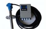
Mount the Transmitter
Remote-mounted transmitters may be mounted on a pipe up to two inches in
diameter or against a flat surface.
Pipe Mounting
To mount the transmitter on a pipe:
1. Attach the mounting bracket to the pipe using the mounting hardware.
2. Attach the 8732 to the mounting bracket using the mounting screws.
Surface Mounting
To surface mount the transmitter:
1. Attach the 8732 to the mounting location using the mounting screws.
To convert from integral mount to remote mount transmitter, consult
Manual Supplement: Integral Mount to Remote Mount Conversion
SENSOR CONNECTIONS
This section covers the steps required to physically install the transmitter
including wiring and calibration.
Rosemount Sensors
To connect the transmitter to a non-Rosemount sensor, refer to the
appropriate wiring diagram in “Universal Sensor Wiring Diagrams” on
page E-1. The calibration procedure listed is not required when used with
Rosemount sensors.
Transmitter to Sensor Wiring
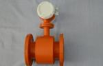
Flanged and wafer sensors have two conduit ports as shown in Figure 2-16.
Either one may be used for both the coil drive and electrode cables. Use the
stainless steel plug that is provided to seal the unused conduit port. Use
PTFE tape or thread sealant appropriate for the installation when sealing the
conduit.
A single dedicated conduit run for the coil drive and electrode cables is
needed between a sensor and a remote transmitter. Bundled cables from
multiple magnetic flowmeters in a single conduit are likely to create
interference and noise problems in your system. Use one set of cables per
conduit run. See Figure 2-16 for the proper conduit installation diagram and
Table 2-3 for recommended cable. For integral and remote wiring diagrams
refer to Figure 2-19.
Applications:
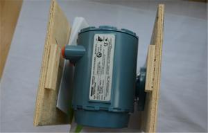
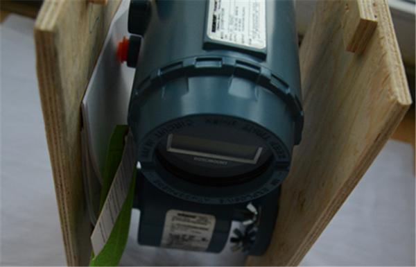
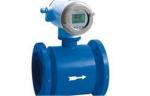
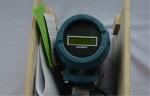
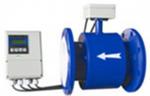
Rosemount 8732 Transmitter - Integral-mount design, backlit display, and explosion proof housing . Available with HART®, FOUNDATION™ fieldbus, or PROFIBUS PA, Device Diagnostics, and Smart™ Meter Verification to improve reliability and performance
Specifications:
Power Consumption | 10 watts maximum |
Switch-on current | AC: Maximum 26 A (< 5 ms) at 250 Vac DC: Maximum 30 A (< 5 ms) at 42 Vdc |
Ambient Temperature Limits | Operating –58 to 165 °F (–50 to 74 °C) without local operator interface 13 to 149 °F (–25 to 65 °C) with local operator interface Storage –40 to 185 °F (–40 to 85 °C) –22 to 176 °F (–30 to 80 °C) with local operator interface |
Humidity Limits | 0–100% RH to 150 °F (65 °C) |
Enclosure Rating | NEMA 4X CSA Type 4X, IEC 60529, IP66 (transmitter) |
Transient Protection Rating | The 8732E has built in transient protection that conforms to EN 61000-4- 4 for burst currents and 61000-4-5 for surge currents. For CE testing the transmitter is compliant with IEC 611185-2.2000 Class 3 which is up to 2 kV and up to 2 kA protection. |
Notice :
Environmental Considerations
To ensure maximum transmitter life, avoid temperature extremes and vibration. Typical problem areas include:
• high-vibration lines with integrally mounted transmitters
• warm-climate installations in direct sunlight
• outdoor installations in cold climates
Remote mounted transmitters may be installed in the control room to protect the electronics from a harsh environment and provide easy access for configuration or service.
Rosemount 8732 transmitters require external power so there must be access to a suitable power source.
|
Rosemount Electromagnetic Insertion Flow Meter with Integral or remote mounting Images |
 Rosemount Orifice Electromagnetic Flow Meter volumetric measurement
 Integrated insertion electromagnetic flow meter / flowmeter for water flowrate
 Rosemount 8750WA Electromagnetic Flowmeter System For Waste water Industry
 Wafer Flowtube Sensor Rosemount 8711 , compact lightweight flanged electro
 Electromagnetic Flow Meter with 4-20 mA , Battery Powered
 Electromagnetic Flow Meter for Pure / sewage water flow measurement
 Split Type Insertion Electromagnetic Flowmeter for liquid flow measurement
 Rosemount 8732 Integral Mount Flow Meter with Remote Mount Magnetic Flowmeter
 Flanged Split Electromagnetic Flow Meter with RS 485 , High Performance